
Collection 02 · Physical + digital systems
Engineering
Lab.
A visual record of measurement, simulation, CAD exploration, testing, and validation—presented at exactly the level the current evidence supports.
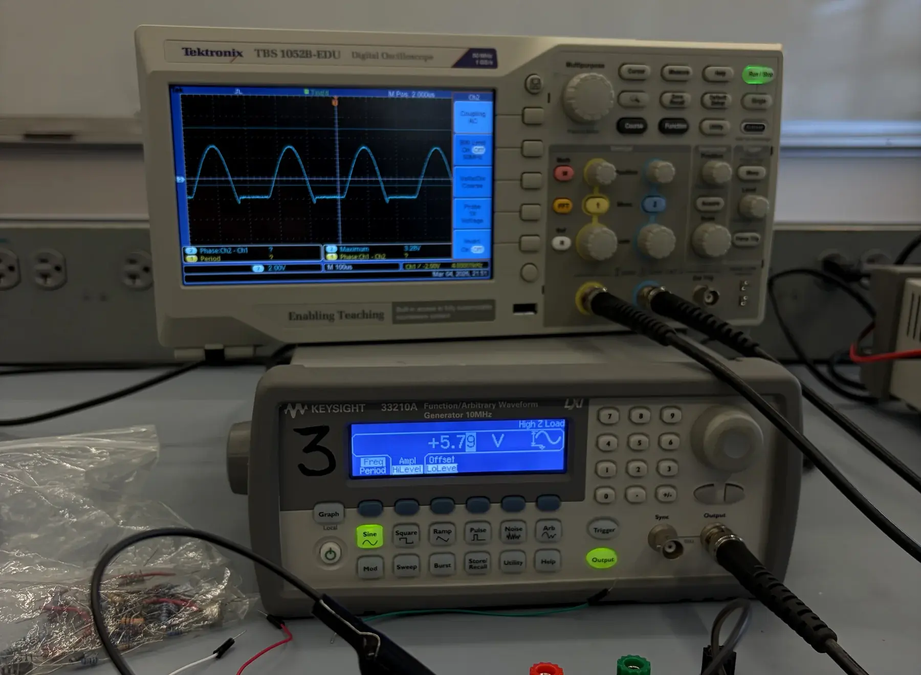
01 / Engineering Lab overview
A collection built from real artifacts.
The current record spans electronics work associated with EET 118, oscilloscope measurement, Logisim simulation, and Fusion 360 studies. Together, the artifacts show a practice of observing, testing, simulating, and documenting physical and digital systems.
- Association
- EET 118
- Media
- 7 real engineering artifacts
- Method
- Inspect · test · document
02 / Electronics and measurement
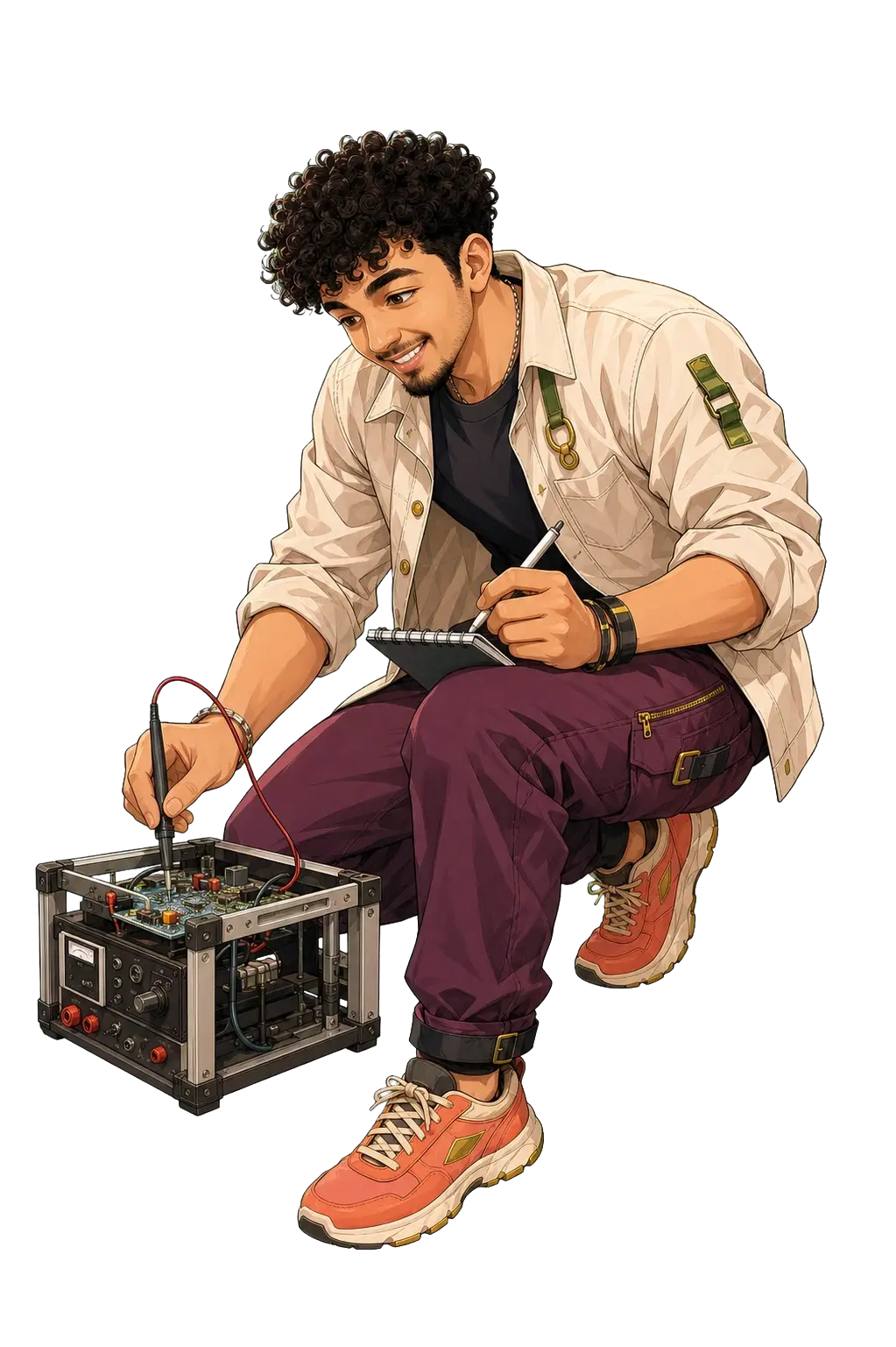
The instrument display is the evidence.
These photographs document an electronics bench, oscilloscope traces, probes, a function generator, a multimeter, and physical circuit work. Captions describe only what can be seen.
Verified report context
EET-118 — EXPERIMENT #6C
Dated Wednesday, March 25. The report covers rectifier/filter calculations involving DC voltage, ripple voltage, RMS voltage, percentage error, and total RMS voltage.
- Recorded capacitance
- 58.1 μF
- Recorded board
- Board #21
03 / Digital logic and simulation
Follow the visible signal paths.
The repository contains one Logisim screenshot. Four-bit A and B inputs, blocks labeled “Unsigned” and “2sComp.,” selection components, inversion gates, and three outputs are visible. The screenshot preserves the signal-path structure for inspection.
- Digital Logic Design
- Logisim simulation
- Testing and debugging
- Functional validation
04 / CAD and physical design
Read form, fit, and visible structure.
Two Fusion 360 screenshots preserve the actual geometry and make their edges, mounting points, supports, bracing, plates, and cylindrical forms available for close inspection.
05 / Engineering and testing process
A process the evidence can support.
- 01
Set up
Connect the physical or simulated system and make the observable points available.
- 02
Observe
Use instrument displays or simulation state to inspect behavior.
- 03
Test
Exercise the work, compare observations, and identify behavior that needs investigation.
- 04
Debug
Trace connections, signal paths, and setup choices before repeating a test.
- 05
Document
Keep screenshots, photographs, calculations, and source notes tied to the work they describe.
06 / Skills demonstrated
Work across physical and digital systems.
07 / Real evidence gallery
Inspect the source material.
Every item opens into a larger view. Deployment copies are optimized and metadata-free; the original repository files remain preserved.
08 / Reflection and next steps
Better documentation makes better engineering visible.
The strongest thread in this collection is the movement from an object or circuit to an observable state: connect it, inspect it, and preserve the result. The next documentation pass should make those relationships explicit at capture time.